2.5D geometries (vertically extruded polygons) can be created in UrbanMetrix. More complex 3D geometries have to be imported as OBJ files.
Specifications
- Only one OBJ file per object (one for custom obstruction, one for project sketch, etc.) can be uploaded.
- The model must be in form of one unique object (even for multiple volumes).
- The OBJ mesh should be water tight.
- The coordinates in the file must be in x,y,z format.
- The Coordinates Reference System (CRS) must be defined.
- The unit of measure need to be in METERS.
- Only faces with maximum 4 vertices are accepted.
How to prepare geometries in Rhinoceros 3D
1. Units
First of all make sure your model is in METERS: command Units.

If your model was in Millimeters for instances, then select the below option. To double check, command Distance and measure a known length.

2. Simple Water-tight mesh
To create a simple water-tight shell mesh, it is recommended to create such volume using the NURBS tools.
Option A: Start from scratch with a model on a locked layer
- Create Polylines, Extrude and Cap.
Option B: Start from a Mesh model
- Select the uppermost Slab surfaces
- Type toNURBS, OK
- SelLast then MergeAllCoplanarsFaces
Option C: Start from a NURBS model on a locked layer
- Select the uppermost Slab surfaces using the CTRL+Click on such surfaces.
- Type DupFaceBorder to get the outside curves. Type Join to be sure they are connected.
- Type PlanarSrf to get surfaces output.
- Type ExtrudeSrf then move the mouse towards the bottom.
- Go into a side-view and drag a selection window from top left to bottom right while pressing CTRL+Shift around the bottom surfaces of the newly created extrusion.
- Then move the Gumball Blue square towards the center of the Gumball to make them all at the same level.
- Or with these bottom surfaces selected, type SetPt, only select the SetZ with WorldAxis. press OK, then type 0. Then move these bottom surfaces to a level you wish.
- These bottom surfaces should be located a few meters below the ground surface from UrbanMetrix, way more underground is no problem at all.
For all the options, Use Join or BooleanUnion and MergeAllCoplanarsFaces commands to create a unified shell.
From this geometry, select it and convert it using the Mesh command.
- Select the fewer polygons count as below.
- Check if the result is good enough.

3. Locate and rotate the model
You can locate the origin of your model in one of two ways before exporting:
- Option 1: LOCAL SWISS LV95
Place it directly at the real-world Swiss LV95 coordinates. - Option 2: CUSTOM COORDS
Place it at the local 0,0,0 origin of your 3D software, and input the real-world Swiss coordinates later during the import process in UrbanMetrix.
Tip for precise alignment: Ideally, this origin point should be positioned on a known cadastral boundary corner to allow for easy translation toward the LV95 coordinate system.
On the above website, turn on the Geocatalo / Cadastre (...) / Availability of the PLR Cadastre.
Locate your site and Right+Click the point your model origin should be placed.

Copy in your ClipBoard the CH1903+ / LV95 Coord.
Mark down the Elevation in METERS too.
In a text editor, rewrite the pasted coordinates
Format for Rhino
Input : 2'718'185.63, 1'096'456.02 , 277.7m
Output : 2718185.63,1096456.02,277.7
(Note the formatting and NO SPACING)
In Rhino, select the Mesh you want to import in UrbanMetrix.
Type Move, click on 0,0,0, paste the ClipBoard content with the LV95 coordinates.
Type ZS to Zoom on your Selection and it should be in the new coordinates.
4. Export OBJ
Select the mesh and type Export.
Select the folder you want to export it in. Select the format .OBJ. Unselect all the boxes and press Options.

Make sure the export options are as below:


5. Import your model in a new UrbanMetrix Grid
Once a project has been created, click on Add Grid.
Follow the instruction on Add Grid and then tick the Project Sketch. Select the file to upload. Follow the same procedure if you have a Custom Obstruction you want to add to your site. Please note that the Project Sketch and the Custom Obstruction must be two separate OBJ models.
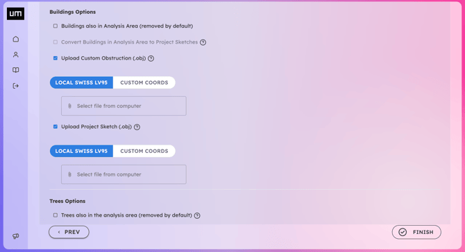
When importing an OBJ file, you must align your 3D model with the real-world geography of the site. In UrbanMetrix, you can achieve this by selecting one of the two available positioning options depending on how your file was prepared:
Option 1: LOCAL SWISS LV95
Select this option if your model is already positioned using absolute real-world coordinates in your 3D modeling software (as shown at point 3 of this article).
-
Find the exact Swiss X, Y, and Z coordinates of your site on the geographical map (you can easily retrieve them from map.geo.admin.ch ).
-
Inside your 3D modeling/CAD software, move your model so that its position matches those exact Swiss coordinates.
-
Export the file as an OBJ. Upon import, UrbanMetrix will read the coordinates and automatically snap the model to its correct location.
Option 2: CUSTOM COORDS
Select this option if your model was built around the local origin (0,0,0) of your 3D modeling software.
-
Inside your 3D modeling software, place a specific reference point of your building (e.g., a specific corner or the center of the footprint) at the global origin (0,0,0).
-
Export the file as an OBJ and import it into UrbanMetrix.
-
In the setup panel, enter the real-world Swiss X, Y, and Z coordinates corresponding to that 0,0,0 anchor point to position the model on the map. You can find these coordinates on map.geo.admin.ch
(Note: If needed, you can also manually adjust the model's horizontal rotation).
Click Finish and wait for the file to reach the server.
Create a simple Geodata with terrain and buildings to test it before further work.