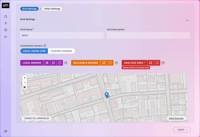
- Trace the Legal Border over the property boundaries to serve as a visual reference. It can be drawn either by hovering over cadastral parcels or by manually drawing a polygon or rectangle.
- Trace the Analysis Area, often set as the Buildable Border while respecting required setbacks. It can be drawn either by referencing another area or by manually drawing a polygon or rectangle.
- Set the Grid Resolution. If the value is known, you can use the building's floor-to-floor height. For small sites, you may use fractions (1/3), and for large sites, multiples (2x) of this value.
- Set Grid Height, typically matching the maximum building height.
- Set Grid Angle, Use the default N-S direction or align it with the primary border or facade. You can also click on any edge of your analysis area to copy its angle value, then paste it into the input box.
- To retrieve the absolute terrain height at a specific point, useful for setting a Custom Grid Elevation or for Flatten Close Terrain, visit MapGeoAdmin, enter the site address, and right-click on the desired point.
- If Flat Top is selected the top of the grid will be flattened at the height of the lowest point of the top. Otherwise, it will follow the morphology of the terrain.
- Define additional parameters influencing the 3D Grid of Sensor Points on the following page.
- You can upload an OBJ 3D model of your project building (Project Sketch) or customized context buildings (Custom Obstruction) in the Geodata. For more details, follow the instructions in the dedicated article: Import OBJ Files.
- Review your settings and click Finish to finalize the Grid creation. Your Grid will be generated instantly.